Transmission Line Equations
Prameters
The different transmission line parameters are as follows:
1. Inductance (L)
2. Capacitance (C)
3. Shunt Conductance (G)
4. Series Resistance (R)
All of these parameters are specified as per unit length basis.
The general relations among these parametes are:
1. L * C = μ * ε
2. G / C = σ / ε
Transmission Line Equations
Consider a short section of transmission line as shown in given figure:
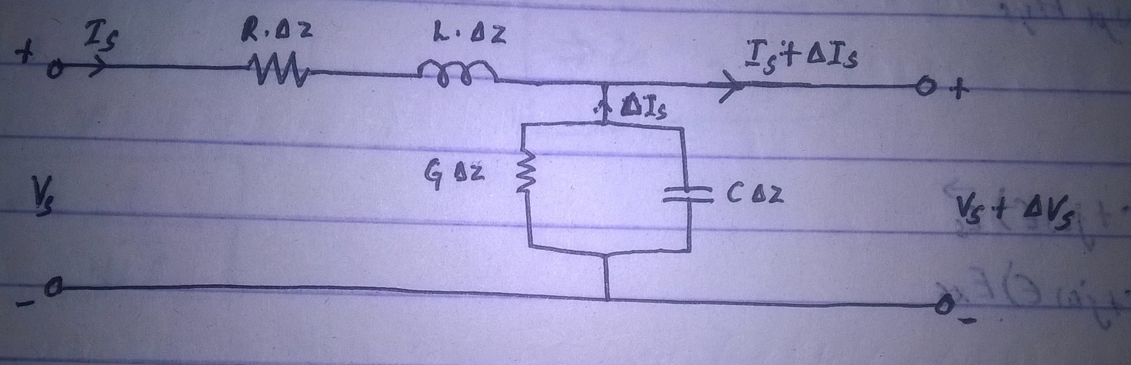
Here, the moder is a section of length Δz containing resistance R.Δz, inductance L.Δz, conductance G.Δz and capacitance C.Δz.
Applying KVL;
V(s) - I(s) * (R + jwL).Δz = V(s) + ΔV(s)
or, ΔV(s) / Δz = - (R + jwL) * I(s)
or dV(s) / dz = - (R + jwL) * I(s)
Applying KCL;
I(s) - (G + jwC) Δz (V(s) + ΔV(s)) = I(s) + ΔI(s)
or, ΔI(s) = - (G + jwC) Δz (V(s) + ΔV(s))
Since, Δz.ΔV(s) is negligible;
or, ΔI(s) = - (G + jwC) Δz V(s)
or, ΔI(s) / Δz = - (G + jwC) V(s)
or, dI(s) / dz = - (G + jwC) V(s)
From Maxwell's equation;
∇ × E(s) = -jwμ H(s)
or, dE(xs) / d(z) = -jwμ H(ys)
Also,
∇ × H(s) = (σ + jwε) E(s)
or, dH(ys) / d(z) = - (σ + jwε) E(xs)
We have,
E(xs) = E(xo) * e ^ (γz)
Replacing E(xs) by V(s) and E(xo) by V(o):
V(s) = V(o) * e ^ (γz)
Also,
γ = √ [ jwμ (σ + jwε)]
γ = √ [(R + jwL) (G + jwC)]
γ = √ [(R G - w^2 L C) + j w (R C + G L)]
γ = α + jβ
The wavelength is the distance that provides phase shift of 2π radian.
So, λ = 2π / β
Also,
v = w / β
For Lossless Transmission:
α = 0
R = G = 0
So,
γ = α + jβ = jβ = jw √(LC)
β = w √(LC)
v = w / β = 1 / √(LC)
We have,
V(s) = V(o) . e ^ (γz)
I(s) = V(s) / η = (V(o) . e ^ (γz)) / Z(o) = V(s) / Z(o)
where,
η = Z(o) = Characteristics Impedandce = √ [(R + jwL) / (G + jwC)] = √ [(jwμ) / (σ + jwε)]
- Characteristics impedance is defined as the ratio of positive travelling voltage wave to current wave at any point of line.
At l = ∞, Z(o) = constant
- Reflection Coefficient is given by:
Γ = V(o)- / V(o)+ = (Z(02) - Z(01)) / (Z(02) + Z(01))
where, Z(02) = Z(L) and Z(01) = Z(o)
- Transmission Coefficient is given by:
τ = V(L) / V(o) = 1 + Γ = 2Z(L) / (Z(L) + Z(o))
- Standing wave ratio is given by:
S = V(max) / V(min) = (1 + |Γ|) / (1 - |Γ|)
- Input Impedance is given by:
Z(in) = Z(o) * [Z(L) + j Z(o) tanβl] / [Z(o) + j Z(L) tanβl] at Z = - l
Matched Transmission Line
The transmission line is said to be matched if and only if Z(o) = Z(L).
Distortionless Transmission Line
- R / L = G / C
So,
α = √(RG)
β = w √(LC)
v(p) = 1 / √(LC)
- Z(o) = √(R / G) = √(L / C)
- α is independent of frequency (f)
- β linearly depends on frequency (f)
Telephone Cables
In case of telephone cables, R/L >> G/C.
To obtain distortionless condition,
a) G can be increased, but it will greatly increase attenuation.
b) R can be reduced, but it results in large diameter conductor.
c) C can be reduced, but has no practical limit.
d) L can be increased by inductive loading, which is the most suitable method.
Impedance Matching, Quarter Wave Transformer, Single Stub Matching and Double Stub Matching
Impedance Matching
- Generally, in a line reflected wave exists, because of which Z(o) != Z(c). This condition is known as mismatched condition.
- For a matched line, following conditions should be true:
|Γ| = 0
|τ| = 1
Quarter Wave Transformer
- It inserts transmission line λ/4 (with Z(in) = Z(o)) prior to load line.
- λ/4 section is known as quarter wave transformer.
Z(in) = Z(o) * [Z(L) + j Z(o) tanβl] / [Z(o) + j Z(L) tanβl]
For l = λ/4, βl = 2π / λ * λ / 4 = π / 2
Dividing numerator and denominator by tanβl and taking limit as βl --> π / 2;
Z(in) = Z(o)^2 / Z(L)
Z(o) = √(Z(in) Z(L))
For quarter wave transformer,
Z(o)' = √(Z(in) Z(L)) = √(Z(o) Z(L))
The reflected wave is eliminated only at desired wavelength.
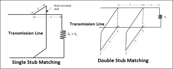
Single Stub Matching
- It uses one shorted stub of length l paced at distance d from load.
- The stub has same characteristic impedance as main line.
- Matching is achieved by varying location of stub and its length.
- Admittance = Y(o) + j β
- Susceptance = -jβ
Double Stub Matching
- It uses two stubs.
- The locations of the stubs are fixed.
- Matching is achieved by adjusting the length of stubs.
Numerical Problems of Transmission Line
Figure: Quarter wave transformer
Figure: Single and Double Stub Matching
Numericals:
1. Given the value of R = 0.1 ohm/m, L = 0.2 μH/m, G = 10 μmho/m, C = 100 pF/m and w = 10^8 rad/s.
Find α, β, γ, v and Z(o).
We know that :
R + jwL = 0.1 + j 20 = 20 < 89.71 °
G + jwC = 0.01 < 89.94 °
So, γ = √[(R+jwL) (G+jwC)] = √[(20 * 0.1) < (89.71 + 89.94)] = √[ 0.2 < 179.65 ] = 0.447 < 89.825° = 1.365 * 10 ^ -3 + j 0.4469 /m
Also,
α = 1.365 * 10 ^ -3 Np/m
β = 0.4469 rad/m
v = w / β = (10^8) / 0.4469 = 2.237 * 10 ^ 8 m/s
Z(o) = √[(R+jwL) / (G+jwC)] = √[200 < -0.23°] = 14.14 - j 0.115 ohm
2. For a air transmission line,
Z(o) = 70 ohm
f = 100 * 10 ^ 6 Hz
β = 3 rad/m
Calculate inductance (L) and capacitance (C). Also find R and G.
Air line is a loss less line
So, R = G = 0
Now,
α = 0,
β = w √ (LC) = 2πf √ (LC)
or 3 = 2π * 10 ^ 8 √ (LC) ................ Eqn 1
Also,
Z(o) = √ (L / C)
or 70 = √ (L / C)
or √L = 70 √C ..................... Eqn 2
On solving equation 1 and 2, we get:
C = 68.2 pF/m
L = 334.4 nH/m
3. For a loss less line:
Z(o) = 50 ohm
l = 30 m
f = 2 MHz
Z(L) = 60 + j 40 ohm
v = 0.6c.
Find Γ, VSWR and Z(in).
Γ = (Z(L) - Z(o)) / (Z(L) + Z(o))
Γ = (60 +j 40 - 50) / (60 +j 40 + 50)
Γ = (10 + j40) / (110 + j40)
Γ = (41.23 < 75.96°) / (117.047 < 19.98°)
Γ = 0.35225 < 55.98°
Again,
VSWR = (1 + |Γ|) / (1 - |Γ|) = 2.087
Also,
βl = w/v * l = 120°
So,
Z(in) = Z(o) * [Z(L) + j Z(o) tanβl] / [Z(o) + j Z(L) tanβl] = 50 (0.479 + j 0.027
-by SURAJ AWAL

Ⓒ Copyright ESign Technology 2019. A Product of ESign Technology. All Rights Reserved.