Physical Layer
Physical Layer and its Functions
- Physical layer is a layer of OSI network model which is used to connect one sender with possibly more receivers.
- It is the actual transmission medium of bits.
- It is the only layer that deals with the physical connectivity of two different nodes.
- It defines hardware equipment, cabling, wiring, frequencies and pulses used to represent binary signals.
- The data link layer provides data frames to physical layer which converts them to electrical pulses that represent binary data.
Transmission Impairments
1. Attenuation
- It is the process of losing strength of signal as it covers distance.
- The receiver needs strong signal in other to interpret the data accurately.
2. Dispersion
- It is the process of spreading and overlapping signals when they travel through a medium.
3. Distortion / Delay
- The bits transmitted through a medium should reach the destination in proper sequence.
- Due to speed and frequency of signal not matched properly, the signal reaches destination in arbitary sequence causing errors in data. This process is called distortion.
4. Noise
- The random disturbance or fluctuation in signal which may distort the actual information is called noise.
- The types of noise are:
a) Thermal noise = Due to heat generated in conductors of a medium.
b) Intermodulation noise = Due to interference caused by multiple frequencies sharing the same medium.
c) Crosstalk = Due to foreign signal entering into the media.
d) Impulse noise = Due to irregular disturbances like lightening.
Latency and Throughput
- Latency is the time taken by a particular packet to reach the destination from source.
- Jitter is delay when the packet has different time every next data transfer.
- Throughput is the amount of data that can traverse through a given medium at a time.
- Throughput is measured in bits per second (bps).
Digital Transmission
- Data may be analog or digital.
- For data transmission using computer, it must be converted to digital signals.
Digital Data to Digital Signal
1) Line Coding
- It is the process of converting digital data into digital signals.
- Unipolar encoding uses a single voltage level to represent data. To represent 1, high voltage is transmitted and to represent 0, no voltage is transmitted.
- Polar encoding uses multiple voltage levels to represent binary data.
- Bipolar encoding uses three voltage levels ( positive, negative and zero ).
2) Block Coding
- The redundant bits are used to ensure accuracy of received data frames.
- This process is called block coding.
- It is represented by mB/nB ( m bit block is represented with n bit block where n > m.)
- It involves division, substitution and combination.
Analog Data to Digital Signal
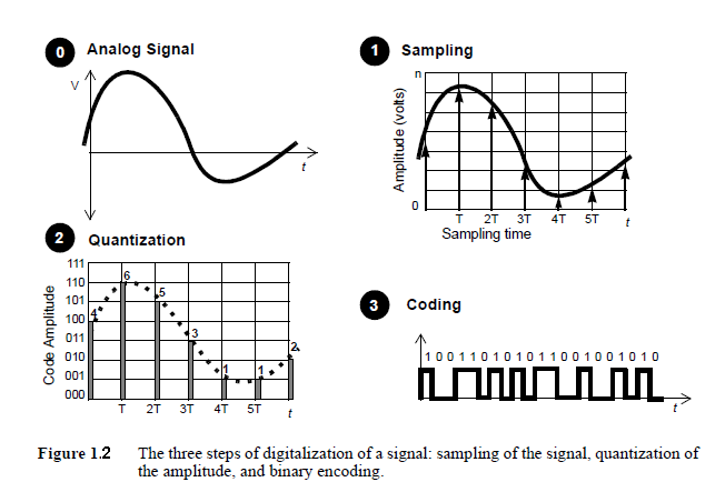
1) Pulse Code Modulation (PCM)
- It involves three steps:
a) Sampling
b) Quantization
c) Encoding
Transmission Media
- Transmission media is the means through which communication takes place in computer network.
- It is a media over which information is transmitted between two computer systems.
- It is categorized as guided and unguided media.
Twisted Pair Cable
- It is a transmission media made of two plastic insulated copper wires twisted together to form a single media.
- Only one wire carries actual signal and the other one is used for ground reference.
- The twisting helps in reducing electromagnetic interference and crosstalk.
- It is of two types : STP and UTP cable.
- In computer network, Cat-5, Cat-5e and Cat-6 UTP cables are used, for which RJ45 connectors are used.
Coaxial Cable
- It is made of two wires of copper.
- The core lies in the center and is made of solid conductor.
- The core is enclosed in an insulating sheath.
- The second wire is wrapped around over the sheath which is also encased by insulator sheath.
- The setup is again covered by plastic cover.
- It is capable of carrying high frequency signals.
- The wrapped structure prevents from noise and crosstalk signals.
- BNC connector is used.
Fiber Optics Cable
- It works on the principles of total internal reflection of light.
- The core is made of high quality glass.
- From one end light is emitted, it travels through it and at the other end, the light detector detects light stream and converts it to electric data.
- It provides high transmission speed.
- It may be single mode or multimode fibre.
- Single mode is capable of carrying a single ray of light and multi mode can carry multiple beams of light.
- The connectors used are Subscriber channel and Straight tip.
Line of Sight
- It is a wireless signal propagation characteristics in which waves travel in a direct path from the source to the receiver.
- It is possible at frequency above 30 MHz.
- Any obstructions between transmitter and receiver will block the signal.
Satellite
- Satellite communication uses artificial satellite that relays and amplifies radio telecommunication via a transponder; thus creating a communication channel between transmitter and receiver.
- Wireless communication uses em wares to carry signals which require line of sight and are obstructed by curvature of the Earth.
- The frequency bands are allocated to organizations to minimize the risk of signal interference.
Multiplexing and Switching
Multiplexing
- It is the technique of dividing high capacity medium into low capacity logical mediums so as to process different transmission streams simultaneously over a shared link.
- All the communication mediums are capable of multiplexing.
- Multiplexer is used to divide a physical channel and allocate each channel to each sender.
- Demultiplexer is used to identify each of the data contained in a single medium and sends to different receivers.
Frequency Division Multiplexing
- It divides carrier bandwidth in logical channels and allocates one user to each channel.
- Each channel has some specific frequency which do not overlap with other channels.
- Guard bands separate the channels.
Time Division Multiplexing
- The channel is divided into time slots and each user can transmit data within the provided time slot only.
- Both ends must be synchronized.
- Signals from different channels traveled in interleaved path.
Wavelength Division Multiplexing
- It is conceptually similar to FDM but uses light as signals and wavelength for channel division.
- On each wavelength, TDM can be done.
Code Division Multiplexing
- It allows users to full bandwidth and transmit signals all the time using a unique code.
- Multiple signals can be transmitted over a single frequency.
Switching
- It is the process of forwarding packets coming in from one port to a port leading to destination.
- When data comes on a port, it is called ingress.
- When data leaves a port, it is called egress.
- Connectionless switching is the one in which data is forwarded based on forwarding tables without necessity of handshake.
- Connection oriented switching is the one which establish circuit along path between both ends before forwarding the data.
Circuit Switching
- When two nodes communicate with each other over a dedicated communication path, it is called circuit switching.
- It requires a pre-specified route for data transfer and no other data is permitted through that path.
- Circuits must be established for data transfer; which may be temporary or permanent.
- The phases in circuit switching are as follows:
a) Circuit establishment
b) Data transfer
c) Circuit breakdown
Packed Switching
- The message is broken down into packets and header of each packet contains switching information.
- The packets can be transmitted independently.
- It does not require more resources to store packets by intermediate devices.
VC Switching
- It is a packet switching in which a path is established between source and final destination through which all the packets will be routed.
- For user, the connection appears to be a dedicated physical circuit.
- Other communications can also share parts of the same path.
Q) Difference between circuit switching and packet switching.
- In packet switching, data is transferred by dividing data into individual packets passing through circuits.
- The route is not exclusively determined.
- Routing algorithms are used.
- In circuit switching, data is transferred through a single dedicated path.
- The route is exclusively determined.
- It requires time to set up channel initially.
- It has predictable and faster performance.
- It has a single point of failure.
Q) Compare switching and multiplexing.
- Multiplexing takes all the inputs and combine them to one output.
- Mux and ‘Demux are used.
- It provides mechanism to share medium among users.
- Switching takes one input and give one output.
- Switching nodes are used.
- It provides mechanism to move data from node to node until they reach destination.
ISDN - Architecture, Interface and Signalling
- ISDN is a digital network which allows digital signals to be sent over existing telephone line.
- It is a communication standards for simultaneous digital transmission of voice, video and data over the traditional circuits of PSTN.
- It is a circuit switched telephone network, which also provides access to packet switched network.
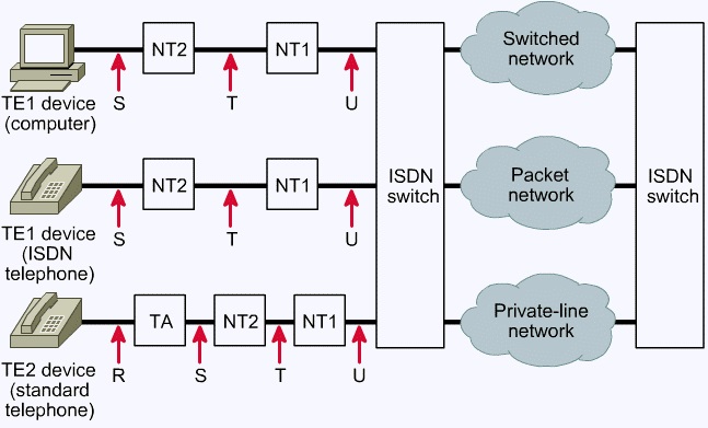
Components of ISDN
1) TE1 devices – The devices compatible with ISDN network.
2) TR2 devices – The devices incompatible with ISDN network.
3) TA – Terminal Adapter that converts signal making it ISDN compatible.
4) NT1 – Connects 4-wire ISDN to 2-wire local loop.
5) NT2 – Directs traffic to and from subscriber devices and NT1.
Interfaces of ISDN
1) R – Connection between TE2 device and TA.
2) S – Connection between devices and NT2.
3) T – Outbound connection from NT2 to NT1.
4) U – Connection between NT1 and ISDN network owned by the telephone company.

Ⓒ Copyright ESign Technology 2019. A Product of ESign Technology. All Rights Reserved.