Introduction to OOAD
Structured System
- System is decomposed into functions.
- Functions and data are modeled separately.
- System components are dependent on each other.
- Inheritance and polymorphism are impossible.
- Reuse is limited.
- It does not reflect real world entities.
- Development process is linear.
- Testing is done in implementation phase only.
Object Oriented System
- System is decomposed into data objects.
- Functions and data are modeled in one place.
- System components are independent of each other.
- Inheritance and polymorphism are possible.
- There is no restriction for reuse.
- It reflects real world entities.
- Development process is iterative and incremental.
- Testing is distributed evenly.
Object Oriented Analysis
- It is the procedure of identifying software requirements and developing software specifications in terms of object model that comprises interacting objects.
- Requirements are organized around objects integrating both data and functions.
- The tasks involved are as follows:
1. Identify objects
2. Organize objects by creating object model diagram
3. Define object attributes
4. Define object actions
5. Describe interaction between objects
- It maps the problem domain directly into a model.
Object Oriented Design
- It is the process of implementing conceptual models produced during analysis phase.
- The technology independent conceptual models are mapped into implementing classes, constraints are identified and interfaces are designed.
- It results a model for the solution of a problem domain.
- The tasks involved are as follows:
1. Define object life cycle
2. Define class relationships
3. Define service logic
4. Complete class definitions
Basic Terminologies
1. Objects
- It is a real world entity that may have physical or conceptual existence.
- Each object consists of data and a set of functions.
- Each object has identity, behavior and state.
- Identity is the instance ID of an object that distinguishes it from other objects in the system.
- Behavior is the methods that the object performs.
- State determines the characteristic properties of an object as well as the values of properties.
For eg: Let transport be an object:
Identity - Bus
Behavior - move(), stop()
State - running, stopped
2. Class
- Class is a description of a set of objects that share the same characteristic properties and exhibit common behavior.
- Object can be created as a member of a class by instantiation.
- Class constitutes of:
a) attributes
b) operations
- Attributes are the data items that define object.
- Operations are the functions that portray the behavior of objects.
3. Method
- Method is a mean by which objects can manipulate data.
- The operations supported by an object are called its methods.
4. Messages
- A message is a method call from one object to another.
- It is a mean by which object interacts.
- Objects communicate with each other by sending messages.
- If obj1 wants obj2 to execute one of its methods, obj1 sends a message to obj2.
5. Abstraction
- It is used to handle complexity.
- It is the process of extracting essential properties relevant to a particular purpose and omitting the unnecessary details.
- It helps in code reuse.
6. Encapsulation and data hiding
- Encapsulation is the process of binding both attributes and methods together within a class.
- Data hiding is the process of giving data access only by its class methods and prevented from direct access outside.
- Encapsulation ensures data hiding.
- It focuses upon the implementation that gives the behavior of an object.
- Data can be accessed from outer object through message passing only.
7. Inheritance
- It is the process of defining new classes out of existing classes by extending and refining its capabilities.
8. Polymorphism
- It is the property that allows using operations in different ways, depending upon the instance they are operating upon.
- Different objects have common external interface but differ in internal structures.
Object Oriented Metrics
1. Weighted Methods per Class (WMC)
- It is the sum of complexities of all class methods.
- It indicates how much effort is required to develop and maintain a particular class.
- Low WMC indicates greater polymorphism.
- High WMC indicates complex class.
2. Depth of Inheritance Tree (DIT)
- It is the length from the class to the root of inheritance tree.
- It calculates how far down a class is declared in inheritance hierarchy.
- High DIT means more methods to inherit making it sophisticated but more reusable.
3. Number of Children (NOC)
- It is the no of direct sub classes of a class.
- It indicates how an application reuses itself.
- High NOC means harder to modify class and requires more testing.
4. Coupling Between Object Class (CBO)
- It is the no of other classes to which it is coupled.
5. Lack of Cohesion in Methods (LCOM)
- It measures dissimilarity of methods in a class.
- High cohesion indicates good class sub division.
- Low cohesion increase complexity.
OOAD Modelling
- Models helps to visualize, specify, construct and document the artifacts of software intensive system.
- OOAD modelling involves development of various diagrams that describes the system under consideration.
- It helps to manage complexity, understand requirements and properly derive the implementation.
Types of Models
1. Conceptual Model
- It is a representation of concepts in a problem domain.
- It is drawn with a set of static structure where :-
a) concepts are associated
b) concepts have attributes
c) concepts have no operations
- It allows implementational constraints.
- It helps to understand the problem requirements.
2. Structural Model
- It is a representation of structure of the problem domain.
- It includes static views of the domain.
3. Behavioral Model
- It is a representation of behavior of the system.
- It includes dynamic views of the domain.
- It allows flow of interactions between the components of the system.
4. Specification Model
- It describes the software abstractions with specifications and interfaces.
- It does not commit implementations.
5. Implementation Model
- It describes the software with implementations in a particular technology.
Requirement Process
- Requirement process is a systematic approach to find, document, organize and track the needs of the users and response on changing requirements of a system.
- Requirements are the aspects that the system must conform.
Requirement Types
1. Functional Requirement
- It describes the behavior of the system.
- It includes user tasks that the system needs to support.
- It is phrased as actions.
2. Non-Functional Requirement
- It describes the properties of the system.
- It is phrases as constraints or negative assertions.
Requirement Elicitation Methods
1. Questionnaire
2. Task Analysis
3. Scenario
4. Case study
Decompositon
- Decomposition is one of the way to manage the complexity.
- Decomposition is the process of decomposing the complex system into smaller parts, each of which can be refined independently.
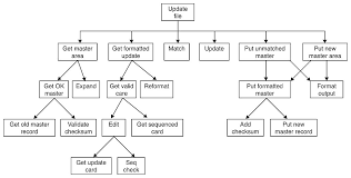
Algorithmic Decomposition
- It involves top-down structured design approach.
- It highlights ordering of events.
- Reuse is limited.
- The decomposition structure chart shows relationships among various functional elements of the solution.
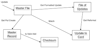
Object Oriented Decomposition
- It is based on key abstraction in problem domain.
- It involves bottom-up approach.
- The system is decomposed as objects.
- It emphasizes the agents.
Role of Hierarchy
- Complexity of a problem can be managed by finding hierarchies of objects and their corresponding classes.
- Object structure illustrates how objects collaborate with one another through patterns of interactions.
- Class structure illustrates common structure and behavior within the system.
Use Cases
Use Case Diagram
- Use case diagram is a representation of a user's interaction with the system that shows relationship between the user and the different use cases in which the user is involved.
- It helps to identify, clarify and organize the system requirements.
- It describes the behavior of the target system from an external point of view.
- A use case diagram consists of following components:
1. Boundary
2. Actor
3. Use case
4. Relationship
Actor
- Actors are the entities that interface with the system.
- Actors are external to the system.
- They may be people, external hardware or other subjects.
- External actors may be primary, supporting and offstage actor.
- Primary actor has user goals fulfilled through services of system under development.
- Supporting actor provides service to system under development.
- Offstage actor has an interest in the behavior of use case.
Use Case
- It is a specification of a set of actions performed by a system which yields an observable result.
- It represents what the actors want your system to do for them.
- Each use case is a complete course of events in the system from a user perspective.
Relationships
1. << include >> relationship
- A usecase may contain functionality of another use case.
- It implies that the behavior of the included use case is inserted into the behavior of the including use case.
- It is expressed as a dotted line labelled << include >> beginning at base use case and ending with an arrow pointing to included use case.
2. << extend >> relationship
- Certain use case may be performed as part of another use case.
- It is optional.
- The base use case can complete without the extended use case.
- It changes the behavior of base use case.
- It implies that the behavior of a use case may be extended by the behavior of another use case.
3. Association
- It indicates the communication between an actor and a use case.
- It is represented by a solid line.
4. Generalization
- It is the relationship between general use case and a special use case.
Example Case:
A coffee vending machine dispenses coffee to customers. Customers order coffee by selecting a recipe from a set of recipes. Customers pay using coins. Change is given back if any to the customer. The service staff loads ingredients into machine. The service staff can also add a recipe by indicating name of coffee, units of coffee powder, milk, sugar, water and chocolate to be added as well as the cost of coffee.
Actors
1. Customer
2. Service Staff
Use Cases
1. Dispense coffee
2. Order
3. Pay coins
4. Payback
5. Load ingredients
6. Add recipe
Use Case Diagram
_1598075150.jpg)
Object Oriented Development Cycle
- The software development approach for object oriented modelling goes through following stages:
1. Analysis
2. Design
a) System design
b) Object design
3. Implementation and Testing
The most successful approach for object oriented software development is Rational Unified Process (RUP). It is an approach that combines iterative and risk driven development into a well documented process description. In RUP, the input to a process is the needs, process is the set of activities to reach goal and output is the software product.
The phases involved in RUP are as follows:
1. Inception:
- The requirements are gathered.
- Feasibility study and scope of the project are determined.
- Actors and their interactions are analyzed.
2. Elaboration:
- Project plan is developed.
- Risk assessment is performed.
- Non-functional requirements are elaborated.
- Software architecture is described.
- Use case model is completed.
3. Construction:
- All the components are developed and integrated.
- All features are tested.
- In each iteration, refactoring is done.
- Stable product should be released.
4. Transition:
- Software product is launched to user.
- Deployment baseline should be complete.
- Final product should be released.
UML: Fundamentals and Notations
Unified Modelling Language (UML)
- UML is an international industry standard graphical notation for describing software analysis and design.
- It is called so because it is a unification and standardization of earlier modeling notations of Booch, Rumbough and Jacobson.
- It provides some types of diagrams, when used within a given methodology, increase the ease of understanding an application under consideration.
Model Diagrams in UML
- The diagrams that are used to visualize the models of the system are called as model diagrams.
- Constraint specifications help to explain the model diagrams and also indicates its boundary.
UML Views
1. User View:
- It defines the functionalities provided by the system to the users.
- It includes use case diagram.
2. Structural View:
- It defines the structure of the system and is also called static models.
- It includes class diagram, component diagram, object diagram, profile diagram, deployment diagram and package diagram.
3. Behavioral View:
- It captures how objects interact with each other.
- It shows the time dependent or dynamic model of the system.
- It includes activity diagram, interaction diagram, sequence diagram and state machine diagram.
4. Implementation View:
- It captures the components of the system and their dependencies.
- It includes component diagram.
5. Deployment View:
- It captures how components are deployed into the system.
- It includes package diagram and deployment diagram.
Relationships in UML
1. Dependency (change in one thing affect semantic of dependent things)
2. Association (describe links between objects)
3. Generalization (objects of specialized element substitutable for objects of generalized element)
4. Realization (two classifiers where one specifies contract and other guarantees to carry out the contract)
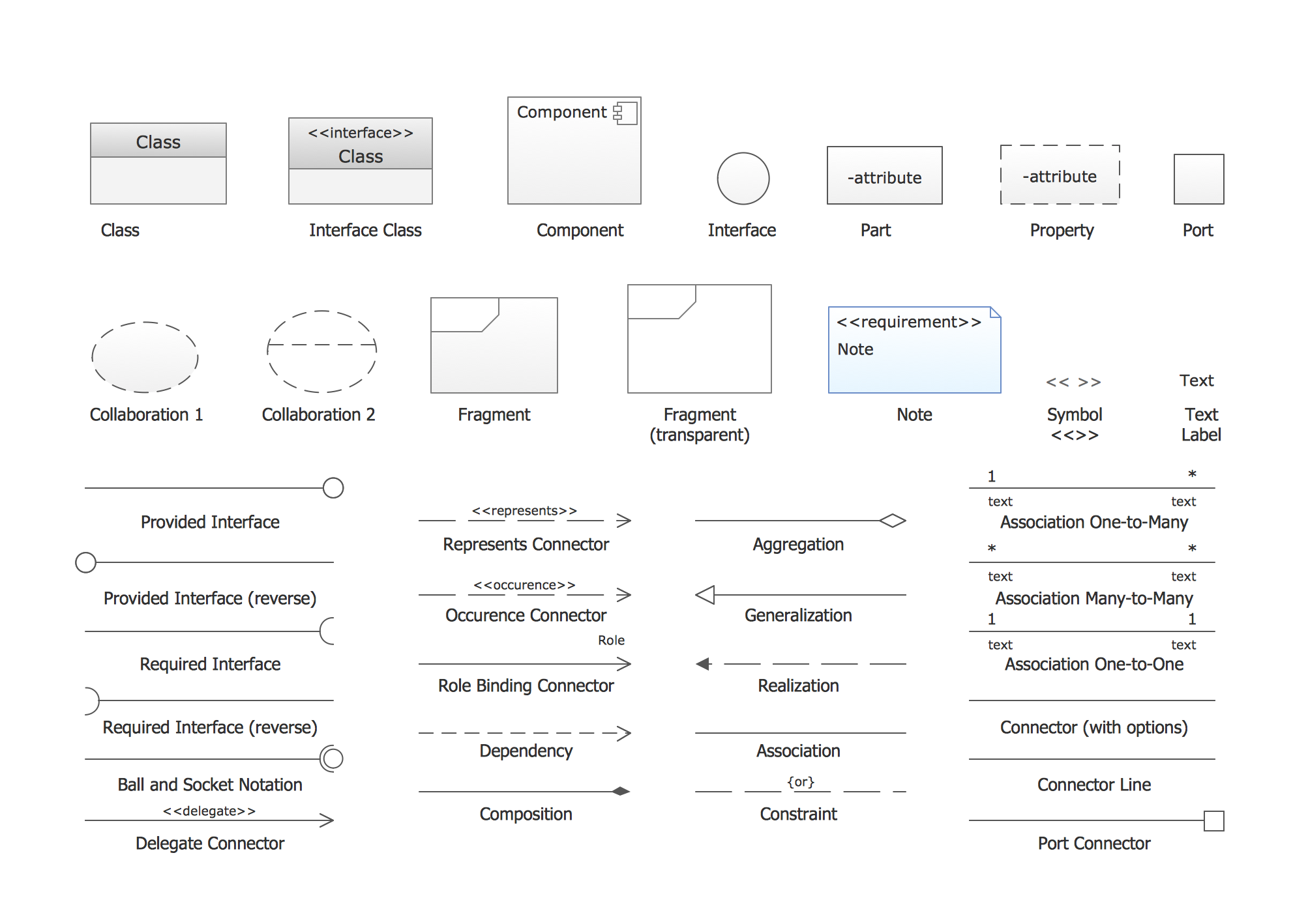
UML Notations
The various notations used in UML are enlisted in the figure below:

Ⓒ Copyright ESign Technology 2019. A Product of ESign Technology. All Rights Reserved.