Building Conceptual Model
Domain Modelling
- Domain model is the important conceptual model that illustrates the noteworthy concepts in a domain.
- It represents the context in which the system must operate.
- A domain model in UML is illustrated with a set of class diagrams omitting the operations.
- It shows the following concepts:
1. Domain classes
2. Associations between domain class
3. Attributes of domain class
- It visualizes and relates concepts of the domain.
Noun Phrase Analysis
- It is the method to find the domain classes.
- Identify the nouns and noun phrases in the textual descriptions of domain.
- Consider them as candidate conceptual classes or attributes.
Adding Associations and Attributes
- Association is the relationship between classes.
- The ends of association may contain multiplicity.
- Multiplicity refers to the numerical relationship between instances of the class.
- Associations should be named with verb phrase in a readable and meaningful way.
- Association name starts with a capital letter.
- Each end of an association is called role.
- Two classes can also have multiple associations.
- Attributes is a logical data value of an object.
- Attributes are shown in second compartment of class box.
- Attribute name is compulsory.
- type and other information are optional.
- The basic syntax is:
visibility name : type multiplicity = default { property - string }
- The derived attributes have a '/' symbol before attribute name.
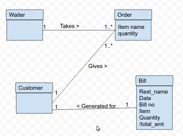
Create a domain model : Example 1
XYZ restaurant in Kathmandu would like to automate its building service. A waiter takes order for each table in restaurant along with order details (item name and quantity). Customers are allowed to order more items after their first order. A bill is generated at the end for each customer having details (restaurant name, date, bill no. item, quantity, and total amount)
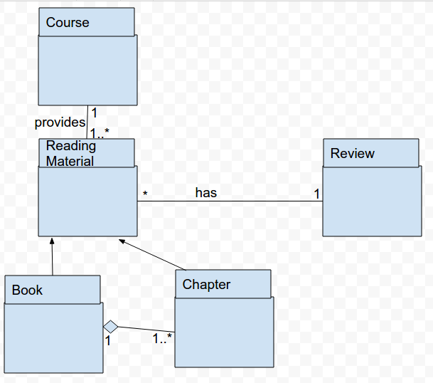
Create a domain model : Example 2
Courses may have recommended items of Reading material, which may be either Books or individual chapters. Items of reading material may also allow user or floppy for every NFA there is for have reviews associated with them.
Representation of System Behavior
- System behavior describes what a system does.
- It hides the implementational details of how system performs.
- It provides the dynamic model of the system.
- A system behavior is depicted as a black box.
- It must shows the reaction of system with external events, timer events and faults with a time frame embedded within it.
- System behavior can be represented by:
1. Use Case
2. System Sequence Diagram (SSD)
3. Operation Contracts
System Sequence Diagram
- Actor generates events by requesting something to the system.
- The request event initiates an operation in the system.
- Ordering of events should follow their order in the scenario.
- SSD can be constructed from use case as:
a) Draw system as black box on right side.
b) For each actor, draw stick figure and lifeline.
c) For each events that each actor generates, draw message.
Operation Contracts
-It gives detailed representation of system behavior.
- Contract describes outcome of executing system operation in terms of state changes to domain objects.
- It is a document containing:
1. Operation
2. Cross Reference
3. Pre conditions
4) Post conditions

Ⓒ Copyright ESign Technology 2019. A Product of ESign Technology. All Rights Reserved.