Polling vs Interrupt
Interrupt
- Interrupt is a signal send by an external device informing the processor that it is ready for communication and requests attention to perform a particular task. It is useful to interface I/O device that provide or require data.
Polling vs Interrupt:
- Whenever a command is given to the device, the device driver has a choice as to how it finds out the command has completed. For this purpose, it can either poll the device or can use interrupts.
- In case of polling, the CPU keeps checking status register or flag to indicate if status changes completing the request.
- In case of interrupt, the hardware being controlled will cause a hardware interrupt to occur whenever it needs attention.
- With interrupt. CPU is free to do its task and if something happens, an interrupt is generated to notify the CPU.
- Polling is better if processor has to respond to an event continuously as soon as possible.

Polled Interrupt:
- The processor has general ISR for all devices. The priority of devices is determined by the order in which routine polls each device. The processor checks starting with highest priority device and once it determines the interrupt source, it branches to service routine for that device.
- Here, several external devices are connected to single interrupt line (INTR). When INTR signal is high, the processor saves contents of PC and registers, and then starts the poll from highest priority device.
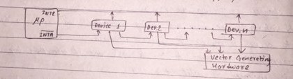
Daisy Chain / Vectored Interrupt:
- It is a faster mechanism. The devices are connected as a chain. When INTR signal is high, the processor generates INTA’ signal to highest priority device. If the device has generated the interrupt, it will accept signal otherwise push INTA’ to next priority device. When INTA’ is accepted, the device responds by placing a word on data lines which becomes interrupt address vector. Here, appropriate ISR is called.
Interrupt Types
External Interrupt:
- It is initiated by external devices.
- Maskable interrupts are those which can be enabled or disabled by executing instructions like EI, DI and so on.
- Non-maskable interrupts are those with highest priority which cannot be enabled or disabled by instructions.
Internal Interrupt:
- It is initiated internally by exceptional conditions.
- The service routines are written by the programmer to take corrective actions during such situations.
- It can also be activated by TRAP instruction.
Interrupt Processing Sequence
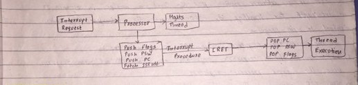
- The I/O unit issues an interrupt signal to the processor for exchange of data between them.
- The processor completes the execution of current instruction before responding to the interrupt.
- The processor sends an acknowledgement signal to the device that issues an interrupt.
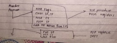
- The processor saves the contents of PSW and PC and transfers control to requested ISR.
- The processor loads PC with location of ISR and fetches the instruction.
- The result is transferred to interrupt handler program.
- After completing interrupt processing, the saved register’s value are retrieved from stack and restored to register.
- It restores PSW, and PC values from stack.
Interrupt Service Routine
- ISR is a software routine that the hardware invokes in response to an interrupt for handling it. ISR processes the interrupt and return control to the main program.
- The execution sequence when ISR is called, are as follows:
a) ISR saves the processor’s registers as both ISR and main program uses the same processor registers.
b) The ISR processes the existing interrupt either in device or in interrupt controller or both with the help of routine or instructions provided in ISR.
c) The saved values of registers are restored.
d) The main program is resumed.
Interrupt Processing in 8085
- The software interrupts in 8085 are from RST 0 to RST 7. The vector address is equal to interrupt number * 8.
- The hardware interrupts in 8085 are TRAP, RST 7.5, RST 6.5, RST 5.5 and INTR.
TRAP (Vector Address = 0024H):
- Non-maskable, first priority, edge and level triggered.
- Must go high and remains high until it gets acknowledged.
- HOLD signal can override TRAP.
- It can be cleared by resetting microprocessor or giving high TRAP acknowledgement.
RST 7.5 (003CH):
- Maskable, second priority, edge triggered.
- I/p goes high and no need to remain high until it is recognized.
- Can be disabled by DI and reorganization of interrupts.
- Can be enabled by EI.
RST 6.5 (0034H) and RST 5.5 (002CH):
- Maskable, level triggered, third and fourth priority respectively.
- Can be enabled by EI.
- Can be disabled by DI, SIM, processor reset and reorganization of interrupt.
INTR:
- Maskable, level triggered and non-vectored.
- After receiving INTA (low) signal, it has to supply address of ISR.
- The sequence of events when INTR signal goes high are as follows:
a) 8085 microprocessor checks INTR signal during execution of each instruction.
b) If INTR signal is high, it completes its current instruction and sends active low interrupt acknowledge signal.
c) In response to acknowledge signal, external device places an instruction OPCODE on data bus.
d) On receiving instruction, 8085 saves address of next instruction on stack and execute received instruction.
Interrupt Processing in 8086
Priority Interrupt Controller
- It is used to determine priorities among devices when they request for interrupt service simultaneously.
- Priorities are determined by encoder.
- It responds to higher level input ignoring lower level input.
- The interrupting device connected at it always has highest priority.
- It includes status register, priority comparator and priority encoder.
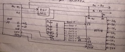
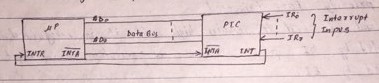
Programmable Interrupt Controller 8259A:
- When 8259A receives interrupt signal, it sends interrupt request signal to INTR of microprocessor and INTA pulses cause the PIC to release vector information on data bus.
- It requires two internal address i.e. A=0 or A=1.
- Low order data bus D0 to D7 are connected to D0 to D7 of 8259.
- The address line A0 of microprocessor is connected to A0 of 8259 to provide internal address.
- 3 to 8 decoder generates chip select signal for 8259.
- Address lines A4, A5 and A6 are used as input to encoder.
- Control signal IO/M’ is used as logic high enables for decoder and address line A7 as logic low enable for decoder.
Interrupt Instructions
1. DI:
- It means Disable Interrupt.
- It is a 1 byte instruction.
- It does not affect any flags.
- All the interrupts except TRAP are disabled.
2. EI:
- It means Enable Interrupt.
- It is a 1 byte instruction.
- It does not affect any flags.
- All interrupts are enabled.
3. SIM:
- It provides additional masking for RST 7.5, RST 6.5 and RST 5.5
- The 8 bit data format is:
4. RIM:
- The status of pending interrupts can be read from accumulator.
- When RIM is executed, 8 bits data is loaded in accumulator.
- The 8 bit data format is:
Interrupt Pins of 8086
INTR:
- Maskable hardware interrupt
- It can be enabled or disabled by using SLI or CLI instructions respectively.
NMI:
- It indicates the non maskable interrupts.
Interrupt Vector Table
- IVT is a memory area where all the interrupts are mapped.
- It is located in memory page 00.
- It holds the vector that redirect the microprocessor to right place when interrupt arises.
- IVT is a 1024 bytes sized table consisting addresses of interrupts.
- Each address is of 4 bytes of form- offset : segment, representing address of ISR to be called when microprocessor receives interrupt.
- The interrupt number (0 to 255) is used as index into the table to get address of ISR.
- When interrupt number is passed as an argument to IVT, it points to required ISR.
- ISR executes its code and finally returns to original statement.
- The model of 4 byte entry is as below:
Interrupt Types
Type 0 (INT 00):
- It is invoked by microprocessor whenever there is an attempt to divide a number by zero.
- ISR displays message “Divide Error”.
Type 1 (INT 01):
- For single stepping, the trap flag must be 1.
- After each instruction, 8086 jumps to 00004H to fetch 4 bytes for CS : IP of ISR.
- ISR dump registers on to the screen.
Type 2 (INT 02):
- Whenever NMI pin is activated, CPU jumps to 00008H to fetch CS : IP of ISR associated with NMI.
Type 3 (INT 03):
- Breakpoint is used to examine CPU and memory after execution of a group of instructions.
Type 4 (INT 04):
- It is invoked when signed number overflows.
- It interrupts on overflow.
Software Interrupt Processing

Ⓒ Copyright ESign Technology 2019. A Product of ESign Technology. All Rights Reserved.