Filter Design by window method - Rectangular, Haanning and Hamming Window
Filter
- Filter is a system that is used to modify certain frequencies relative to others.
- It passes certain frequency components and totally rejects all other.
Linear Phase FIR Filter
- The system function of an FIR filter of length N is given by:
H(z) = ∑n=0to N-1 { h[n] z-n }
- The corresponding frequency response is given by substituting the value of z with ejΩ :
H(ejΩ) = ∑n=0to N-1 { h[n] ejΩn } = H(Ω) . ejϕ(Ω)
where,
H(Ω) is zero phase frequency response
ϕ(Ω) is a phase term
- A filter is called linear phase filter if the phase term has the form of:
ϕ(Ω) = αΩ + β
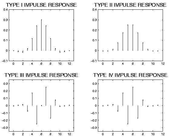
Types of linear phase FIR filter
- A filter will have linear phase if its impulse response is symmetric or anti symmetric.
h[N-1-n] = (+ or -) h[n] for all n
- There are four types of linear phase FIR filters. They are as follows:
1. N odd and h[n] symmetrical (Type I)
2. N even and h[n] symmetrical (Type II)
3. N odd and h[n] asymmetrical (Type III)
4. N even and h[n] asymmetrical (Type IV)
FIR Filter Design using Windows
- FIR filter is designed by window method by simply multiplying the infinitely long impulse response by a window function.
- Let us consider the desired frequency of the digital filter be Hd(ejΩ).
So, the impulse response of the required filter is given by:
hd[n] = 1/2π . ∫-π to π {Hd(ejΩ) . (ejΩn) . dΩ}
- The impulse response obtained by the digital filter may not be of finite duration.
- An approximate FIR filter of finite duration can be obtained by truncating the impulse response. This truncation can be done with the help of a window function such that:
h[n] = hd[n] . w[n]
where,
w[n] is a window function.
Rectangular Window
- Rectangular window is a window function having magnitude 1 for the range of n = 0 to M-1.
- It is denoted by wR[n].
- Mathematically,
wR[n] = 1 for 0 <= n <= M-1
                                  = 0 elsewhere
Let us consider the fourier transform of rectangular window as:
     WR(w) = ∑n = 0 to M-1 { wR(n) . e-jwn }
                                         = ∑n = 0 to M-1 { e-jwn }
From the standard series relation:
WR(w)
= [e-jw*0 - e-jwM ] / [ 1 - a ]
= [ 1- e-jwM ] / [ 1 - e-jw ]
= [ {e-jwM/2 . ejwM/2} - {e-jwM/2 . e-jwM/2} ] / [ {e-jw/2 . ejw/2} - {e-jw/2 . e-jw/2} ]
= [ e-jwM/2 {ejwM/2 - e-jwM/2} ] / [ e-jw/2 {ejw/2 - e-jw/2} ]
= [ e-jw{(M-1)/2} ] * [ sin(wM/2) ] / [ sin(w/2) ]
Comparing with polar form :
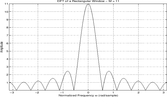
The magnitude response of rectangular window is given by:
| WR(w) | = | [ sin(wM/2) ] / [ sin(w/2) ] |
The magnitude response for M = 11 is shown in figure below:
Problems with Rectangular Window:
- With increase in window length, width of main lobe in frequency response decreases while side lobes are unaffected.
- Large side lobes in W(Ω) cause undesirable ringing in the filter designed.
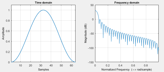
Hamming Window
- Hamming window is given by:
      wH(n) = 0.54 - 0.46 cos (2πn / (M-1)) for n = 0, 1, 2, .......... , M-1
                                          = 0 ; elsewhere
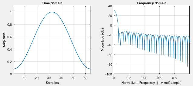
Hanning Window
- Hanning window is given by:
      wHN(n) = 1/2 [ 1 - cos (2πn / (M-1)) ]   for n = 0, 1, 2, .........., M-1
                                          = 0 ; elsewhere
Filter Design by Kaiser Window
- In other windows, width of main lobe and attenuation of side lobes depend only upon window length M.
- Kaiser window allows separate control of these factors.
- Kaiser window is defined as:
     wk(n) = [ Io { β [ 1 - ((n-α)/α)2]1/2} ] / [ Io(β) ]      for 0 <= n <= M
                    = 0 ; elsewhere
where, Io() is 0th order modified Bessel function of first kind.
α = M/2
β is called shape parameter
Design Steps
1. Get desired frequency response Hd(w)
2. Take inverse fourier transform of Hd(w) to obtain hd[n]
3. Decide length of FIR filter
4. Multiply hd[n] by selected window function to get h[n].
Q) Design linear phase filter using Kaiser window to meet the given specification.
The given specification is:
            0.99 <= | H(ejw | <= 1.01 ; for 0 >= w >= 0.19π
            | H(ejw | <= 0.01 ; for 0.21π <= w <= π
From the above specification, we get:
δp = 0.01
δs = 0.01
wp = 0.19π
ws = 0.21π
Now,
Δw = ws - wp = 0.02π
Minimum value of ripple (δ) = min(δp, δs) = 0.01
Attenuation in dB is:
A = -20 log10δ = 40 dB
Cut off frequency is:
wc = { ws + wp } / 2 = 0.2π
Now,
As, 21 <= A <= 50; the value of β is given by:
β = 0.5842 (A-21)0.4 + 0.07886 (A-21) = 3.395
Window width is calculated as:
M = (A-8) / 2.285Δw = 222.88 = 223
The value of α is given by:
α = M / 2 = 111.5
Now, the Kaiser window is defined by:
wk(n) = [ Io { β [ 1 - ((n-α)/α)2]1/2} ] / [ Io(β) ] for 0 <= n <= M
= 0 ; elsewhere
So,
wk(n) = [ Io { 3.395 [ 1 - ((n-111.5)/111.5)2]1/2} ] / [ Io(3.395) ] for 0 <= n <= M
= 0 ; elsewhere
Now,
The low pass filter has desired frequency response of :
Hd(w) = e-jw((M-1)/2) ; for -wc <= w <= wc
= 0 ; elsewhere
Taking inverse fourier transform:
hd(w) = sin[wc (n - (M-1)/2)] / [ π (n - (M-1)/2) ] ; for n != (M-1) / 2
= wc / π ; for n = (M-1) / 2
As the desired filter length is M+1;
hd(w) = sin[wc (n - M/2)] / [ π (n - M/2) ] ; for n != M / 2
= wc / π ; for n = M / 2
As M/2 is not a integer;
hd(w) = sin[wc (n - M/2)] / [ π (n - M/2) ]
= sin[0.02π (n - 111.5)] / [ π (n - 111.5) ] ; for 0 <= n <= M
Hence, the required filter design is obtained by:
h[n] = hd(n) . wn
Q) Design FIR filter having pass band edge frequency w<sub>p</sub> = 0.03π, w<sub>s</sub> = 0.05π and α<sub>s</sub> = 40 dB using appropriate window function.
Here, αs = 40 dB which is close to 44 dB (Hanning window). So, we choose Hanning window for the design of the given FIR filter.
Given:
wp = 0.03π
ws = 0.05π
For Hanning window, width of main lobe = 8π / M = k (2π / M )
So, k = 4
And,
M = k . [ 2π / { ws - wp } ] = 400
The Hanning window function is given by:
wHN(n) = 1/2 [ 1 - cos (2πn / 399) ] for n = 0, 1, 2, .........., M-1
= 0 ; elsewhere
The desired frequency response of LPF is given by:
Hd(w) = e-jw((M-1)/2) ; for -wc <= w <= wc
= 0 ; elsewhere
Taking the inverse fourier transform:
hd(w) = sin[wc (n - (M-1)/2)] / [ π (n - (M-1)/2) ] ; for n != (M-1) / 2
= wc / π ; for n = (M-1) / 2
Hence, the required filter design is obtained by:
h[n] = hd(n) . wHN(n)
Filter Design by Frequency Sampling Method
- The desired frequency response is specified as samples at a set of equally spaced frequencies.
- h(n) = 1/N ∑n = 0 to M-1 { H(k + α) . e-j 2π(k+α) n/M } ; n = 0, 1, ....., M-1
Filter Design by Optimum Approximation
- Optimal filter is a filter that is designed to spread the weighted approximation error between the desired frequency response and the actual frequency response across the passband and stopband of the filter.
- The main aim is to reduce the maximum error.
- The result has ripples in both passband and stopband.
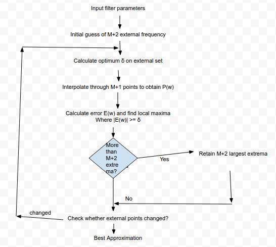
Remez Exchange Algorithm
Definition:
- Remez exchange algorithm is an iterative algorithm to determine the set of filter parameters as required by alternation theorem.
Flowchart:
- The flow chart for Remez Exchange Algorithm is shown in given figure:
Derivation:
The real valued frequency response can be written as:
          Hr(Ω) = Q(Ω) . P(Ω)
where,
  P(Ω) = ∑k = 0 to L {α(k) . cos Ωk}
Q(Ω) = 1 ; case 1
= cos Ω/2 ; case 2
= sin Ω ; case 3
= sin Ω/2 ; case 4
αk are filter parameters.
Let the desired real valued frequency response be Hdr(Ω).
The error between desired and designed frequency response is controlled with weighted error function as:
E(Ω) = W(Ω) [ Hdr(Ω) - Hr(Ω) ]
The weight function is normalized as:
    W(Ω) = δ2 / δ1 ; Ω in pass band
              = 1 ; Ω in stop band
Now,
E(Ω) = W(Ω) Q(Ω) [ Hdr(Ω) / Q(Ω) - P(Ω) ]
Let W'(Ω) = W(Ω) . Q(Ω)
       H'dr(Ω) = Hdr(Ω) / Q(Ω)
So,
E(Ω) = W'(Ω) [ H'dr(Ω) - P(Ω) ]
Now,
The filter parameters should be obtained such that:
minover {α(k)} [ maxw ∈ S { |E(Ω)| }] = minover {α(k)} [ maxw ∈ S { |W'(Ω) [ H'dr(Ω) - P(Ω) ]| }]

Ⓒ Copyright ESign Technology 2019. A Product of ESign Technology. All Rights Reserved.