FIR Filter and Structures
FIR System
- FIR system is a system that has impulse response of finite length.
- It is also called all zero system.
- Consider a causal FIR system with impulse response of form : h[n] = 0 for M-1 < n < 0
The output convolution sum is a finite sum given by:
y[n] = ∑k=0 to M-1 h[k] . x[n-k]
The difference equation is given by:
y[n] = ∑k=0 to M-1 bk . x[n-k]
The system is given by:
Y(z) = ∑k=0 to M-1 h[k] . zk = ∑k=0 to M-1 bk . z-k
IIR System
- IIR system is a system that has impulse response of infinite length.
- If output is computed only in terms of input of sample values, it will require infinite number of mathematical operations.
- The output convolution sum is given by:
y[n] = ∑k=0 to ∞ h[k] . x[n-k]
- The output is expressed recursively using past outputs.
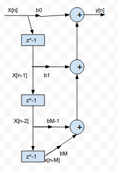
- The difference equation for Nth order IIR system is:
y[n] = ∑k=0 to N ak y[n-k] = ∑k=0 to M bk x[n-k]
- The system function is given by:
H(z) = Y(z) / X(z) = [ ∑k=0 to M bk z-k ] / [ ∑k=0 to N ak z-k ]
Necessity for Different Structure
The major factors that influence our choice of a specific structure are as follows:
1. Computational complexity:
- It refers to the number of arithmetic calculations required to compute an output value for the system.
2. Memory requirements:
- It refers to the number of memory, locations required to store the system parameters, past inputs, past outputs and any intermediate computed values.
3. Finite word length effect:
- It refers to the quantization effects that are inherent in any digital implementations of the system.
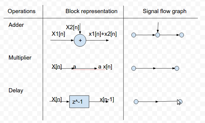
Signal Flow Graph Representation
- It is a network of directed branches connected at nodes.
- Input is at source node and output is at sink node.
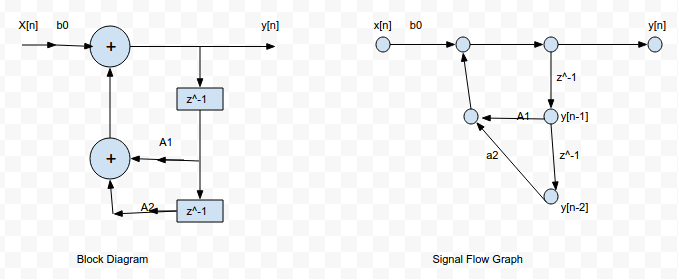
Q) Represent the following in block diagram and signal flow graph:
y[n] = a1 y[n-1] + a2 y[n-2] + b0 x[n]
Structures of FIR System
1. Direct Form
2. Cascade Form
3. Frequency Sampled
4. Lattice Structure
1. Direct Form:
- It is the direct implementation of difference equation or convolution sum.
- The coefficients used to represent system are same as the values of impulse response of the system.
- A FIR system of length M requires M multipliers, M-1 memory locations and M-1 additions.
- It computes output as a weighted linear combination of past M-1 values of input.
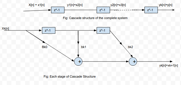
2. Cascade Form:
- The higher order system is realized as a cascade of smaller order sections.
- Second order sections are chosen to avoid the complex coefficients.
- H(z) = πk=1 to K Hk(z)
where,
Hk(z) = bk0 + bk1 z-1 + bk2 z-2 for k = 1, 2, ............., K
3. Frequency Sampled Structure:
- The structure is based on frequency domain specification of the system.
- The frequency response is given by:
H(w) = ∑n=0 to M-1 h[n] . e-jwn
- The samples are:
H[k + α] =∑n=0 to M-1 h[n] . e-j {2π (k+α) / M} n for α = 0 or 1/2
- The impulse response of desired system is:
h[n] = 1/M ∑k=0 to M-1 H[k+α] . e-j {2π (k+α) / M} n for α = 0 or 1/2
- The system function of the desired system is:
H(z) = ∑n=0 to M-1 h[n] . z-n
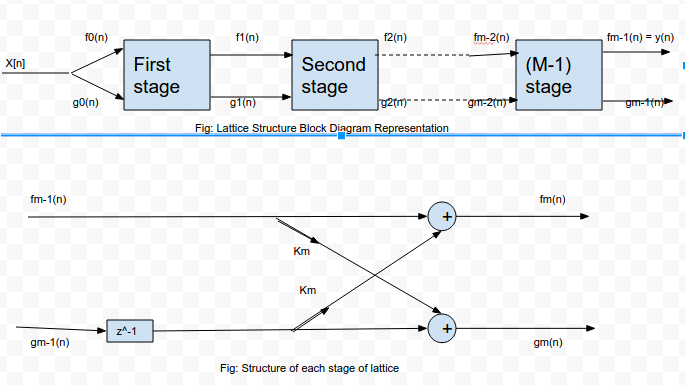
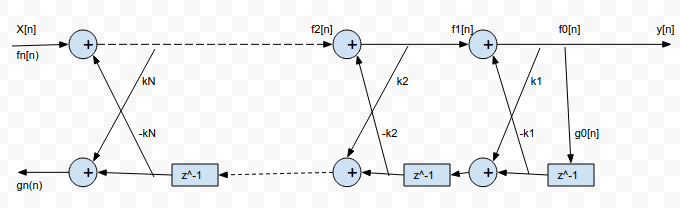
4. Lattice Structure:
- A higher order length FIR lattice looks as shown in given figure with each stage as shown:
- For a lattice with M-1 stages:
fm[n] = fm-1[n] + km . gm-1[n-1]
gm[n] = gm-1[n-1] + km . fm-1[n]
go[n] = fo[n] = x[n]
fm-1[n] = y[n]
- If mth stage output:
fm[n] = ∑k=0 to m αm(k) . x[n-k]
Conversions:
1. From Lattice structure to Direct structure:
Ao(z) = Bo(z) = 1
Am(z) = Am-1(z) + km . z-1 . Bm-1(z)
Bm(z) = z-m . Am(z-1)
2. From Direct form to Lattice Structure:
Am-1(z) = [Am(z) - km . Bm(z)] / [1 - km2]
Bm(z) = z-m Am(z-1)
km = αm(m)
Q)Determine direct form of a three stage (M=4) lattice with coefficients k1 = 1/2, k2 = 1/2 and k3 = 1/4.
We know,
     Ao(z) = Bo(z) = 1
Using, Am(z) = Am-1(z) + km . z-1 . Bm-1(z) and Bm(z) = z-m . Am(z-1) :
A1(z) = A0(z) + k1 . z-1 . B0(z) = 1+1/2 z-1
B1(z) = z-1 . A1(z-1) = 1/2 + z-1
A2(z) = A1(z) + k2 . z-1 . B1(z) = 1+3/4 z-1 + 1/2 z-2
B2(z) = z-2 . A2(z-1) = 1/2 +3/4 z-1 + z-2
A3(z) = A2(z) + k3 . z-1 . B2(z) = 1 + 7/8 z-1 + 11/16 z-2 + 1/4 z-3
Q) Determine lattice representation for H(z)=1+2z<sup>-1</sup>+z<sup>-2</sup>
Here,
      k2 = α2(2) = 1
      A2(z) = H(z) = 1+2z-1+z-2
So, α2(0) = 1
       α2(1) = 2
       α2(2) = 1
And,
B2(z) = z-2 A2(z-1 = 1+2z-1+z-2
Here, A2(z) and B2(z) are same. So it is solved using the formula given below:
am(k) = am-1(k) + am(m) . am-1(m-k)
Now, for m = 2 and k = 1:
a2(1) = a1(1) + a2(2) . a1(1)
or, 2 = a1(1) { 1 + 1 }
or a1(1) = k1 = 1
Hence, the lattice structure has k1 = 1 and k2 = 1.
Q) Realize cascade structure of H(z).
H(z) = 1 + 2z-1 - 3z-2 - 4z-3
        = 1 + z-1 + z-1 + z-2 - 4z-2 - 4z-3
        = (1 + z-1) (1 + z-1 - 4z-2)
        = H1(z) . H2(z)

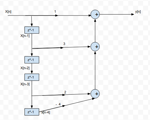
Q) Realize H(z) in direct form.
            H(z) = 1 + 3z-1 + 2z-3 - 4z-4    [All zero system]
or,       Y(z) / X(z) = 1 + 3z-1 + 2z-3 - 4z-4
or,       Y(z) = X(z) + 3z-1 X(z) + 2z-3 X(z) - 4z-4 X(z)
Using inverse Z-transform, we get:
y[n] = x[n] + 3 x[n-1] + 2 x[n-3] - 4 x[n-4]
The direct structure is shown in figure below:
IIR Filter and Structure
1. Direct Form Structure
Direct Form I:
- If y[n] = - ∑k=1 to N ak y[n-k] + ∑k=0 to M bk x[n-k]
- We can write:
v[n] = ∑k=0 to M bk x[n-k]
H1(z) = V(z) / X(z) = ∑k=0 to M bk z-k
- And,
y[n] = - ∑k=1 to N ak y[n-k] + v[n]
H2(z) = Y(z) / V(z) = 1 / (1 + ∑k=1 to N ak z-k)
Direct Form II:
- H(z) = Y(z) / X(z) = [∑k=0 to M bk z-k] / [1 + ∑k=1 to N ak z-k]
- It is obtained by simply interchanging the position of H1(z) and H2(z) in direct form I structure and taking the delay common.
2. Cascade Form Structure:
- To obtain cascade form, the numerator and denominator of a given transfer function H(z) is factored into the product of second order terms.
- H(z) = H1(z) . H2(z) ...................... Hk(z)
3. Parallel Form Structure:
- The given transfer function H(z) is expanded using partial fraction expansion such that:
H(z) = C + H1(z) + H2(z) + ................... + Hk(z)
where,
C is constant
H1(z), H2(z), ...... , Hk(z) are second order sub systems.
- Each second order sub system can be realized by using direct form I or direct form II.
- All these sub systems are then connected in parallel.
4. Lattice Structure
The lattice structure is shown in figure below:
For Ladder Structure
Cm = bm - ∑i = m+1 to M [ ci Qi (i-m) ]
for m = M, M-1, ....................... , 0
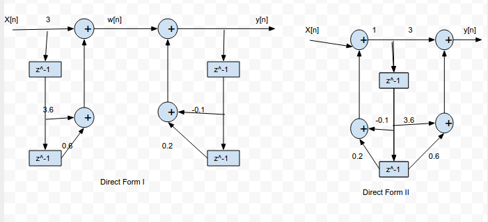
Q) Determine direct forms for y[n].
Given :
       y[n] = -0.1 y[n-1] + 0.2 y[n-2] + 3 x[n] + 3.6 x[n-1] + 0.6 x[n-2]
Taking Z-transform on both sides, we get:
Y(z) = -0.1 z-1 Y(z) + 0.2 z-2 Y(z) + 3 X(z) + 3.6 z-1 X(z) + 0.6 z-2 X(z)
or, H(z) = Y(z) / X(z) = [3 + 3.6 z-1 + 0.6 z-2 ] . 1/[1 + 0.1 z-1 - 0.2 z-2] = H1(z) . H2(z)
The direct form I and II are shown in given figure:
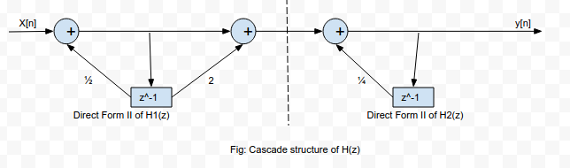
Q) Determine cascade form of y[n].
Given:
      y[n] - 3/4 y[n-1] + 1/8 y[n-2] - x[n] - 2 x[n-1] = 0
Taking Z transform and performing necessary shifting, we can write:
H(z) = Y(z) / X(z) = [1 + 2 z-1] / [(1 - 1/2 z-1) (1 - 1/4 z-1)]
or, H(z) = H1(z) . H2(z)
The cascade structure and other necessary structures for its derivation are shown in given figure:
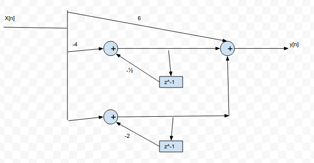
Q) Obtain parallel form realization of H(z).
Given :
           H(z) = [3 {2z2 + 5z + 4}] / [(2z + 1) (z + 2)]
Now,
F(z) = H(z) / z = [3/2 {2z2 + 5z + 4}] / [z (z + 1/2) (z + 2)] = (A/z) + (B/(z+1/2)) + (C/(z+2))
From partial fraction method, we get:
A = z F(z) |z = 0 = 6
B = (z+1/2) F(z) |z = 0 = - 4
C = (z+2)F(z) |z = 0 = 1
So,
H(z) = 6 - (4/(1+1/2 z-1)) + (1/(1+2 z-1))
The parallel form structure is shown in figure below:
Q) Realize system function for all pole system with k1 = 1/4, k2 = 1/4 and k3 = 1/3.
The required system function is of form:
     H(z) = 1 / [a3(0) + a3(1) z-1 + a3(2) z-2 + a3(3) z-3]
Given:
k1 = 1/4
k2 = 1/4
k3 = 1/3
We know that:
km = am(m)
So,
k3 = a3(3) = 1/3
Also, a3(0) = 1
Now,
In general:
am(k) = am-1(k) + am(m) am-1(m-k)
So,
For m = 3 and k = 2:
a3(2) = a2(2) + a3(3) . a2(1)
or, a3(2) = k2 + k3 a2(1) = 1/4 + 1/3 a2(1) ..............................(1)
For m = 3 and k = 1:
a3(1) = a2(1) + a3(3) . a2(2)
or, a3(1) = a2(1) + 1/3 . 1/4 .................................(2)
For m = 2 and k = 1:
a2(1) = a1(1) + a2(2) . a1(1)
or, a2(1) = 1/4 + 1/4 . 1/3 = 5/16
Substituting in equation 1 and 2: we get,
a3(2) = 17/48 and a3(1) = 19/48
Hence,
H(z) = 1 / [1 + 19/48 z-1 + 17/48 z-2 + 1/3 z-3]
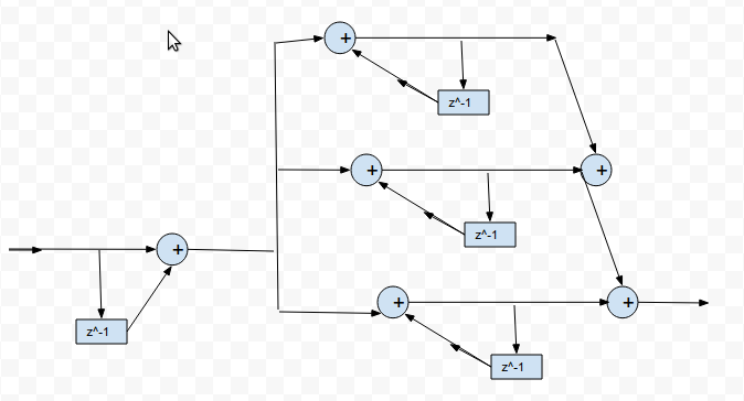
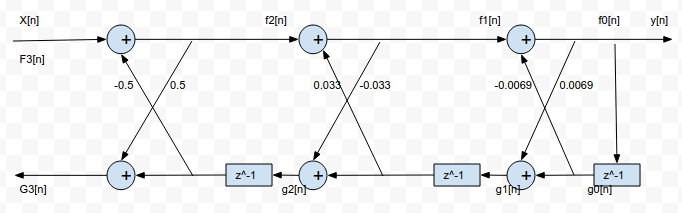
Q) Realize lattice structure of given IIR system.
Given:
        H(z) = Y(z) / X(z) = 1 / [ 1 - 0.01 z-1 - 0.23 z-2 + 0.5 z-3]
Taking inverse Z-transform, we get:
y[n] - 0.01 y[n-1] - 0.03 y[n-2] + 0.5 y[n-3] = x[n]
Also, x[n] = f3[n] = f2[n] + k3 g2[n-1]
We get, a3(0) = 1, a3(1) = - 0.01, a3(2) = -0.03 and a3(3) = 0.5
So, k3 = a3(3) = 0.5 ...........................(1)
We know that:
am-1(k) = [am(k) - am(m) . am(m-k)] / [1 - am(m)2]
For m = 3:
- If k = 1; a2(1) = 0.0067
- If k = 2; a2(2) = - 0.033
So, k2 = a2(2) = -0.033 ..........................(2)
For m = 2:
- If k = 1; a1(1) = 0.0069
So, k1 = k1(1) = 0.0069 ........................(3)
The lattice structure is shown in given figure:
Quantization Effect and Limit Cycle
Quantization Effect
- As the number and coefficients of signal processing may be of infinite length but the register in which they are stored are of finite length, such numbers and coefficients should be quantized which induces errors.
- Truncation is the process of discarding all bits less significant than least significant bit that is retained.
- Rounding is the process of choosing rounded result as b-bit number closest to original number unrounded.
Limit Cycle Oscillation
- When a stable IIR filter is excited by a finite constant input sequence, the output would ideally be zero.
- Due to finite precision arithmetic, non-linearities occurs causing periodic oscillations to occur in the input.
- Such oscillation in recursive system is called limit cycle oscillation.
Example:
Let an IIR filter have difference equation:
        y[n] = x[n] + α y[n-1]      with α = 1/2
If register length 3 bits data and a sign bit and input is:
       x[n] = 0.875 ; n=0
               = 0 ; elsewhere.
n x[n] y[n-1] αy[n-1] Q[.] y[n]
------------------------------------------------------------------
0 0.875 0.0 0 0.000 7/8
1 0 7/8 7/16 0.100 1/2
2 0 1/2 1/4 0.10 1/4
3 0 1/4 1/8 0.001 1/8
4 0 1/8 1/16 0.001 1/8
5 0 1/8 1/16 0.001 1/8
Dead Band
- The range of values in which the amplitudes of the output during a limit cycle are confined is known as dead band.

Ⓒ Copyright ESign Technology 2019. A Product of ESign Technology. All Rights Reserved.