Data Link Layer and its Functions
- It is the second OSI layer that is responsible to hide the underlying hardware details and acts as a medium to communicate for upper layers.
- On sending end, it converts data stream to signals bit by bit and sends over the underlying hardware.
- On receiving end, it picks up data from hardware in the form of signals, assembles them in a recognizable frame format and hands over to upper layer.
- It has two sub layers – logical link control and media access control.
Functions of Data Link Layer
Framing
- It receives packets from network layer and encapsulates them into frames, which is send on hardware bit by bit.
- On receiver, it gets signals from hardware and assembles them into frames.
Addressing
- It provides hardware addressing mechanism which is unique and encoded into hardware at the time of manufacturing.
Synchronization
- It synchronizes both computers when sending data frames on the link for successful transfer.
Error Control
- It helps in detecting errors and recovering actual data bits.
- It provides error reporting mechanism to the sender.
Multi Access
- It provides mechanism for accessing shared media among multiple systems reducing data collision.
Flow Control
- It ensures flow control to enable both devices to exchange data on same speed.
Framing
- It deals with breaking of bit stream up into frames.
- The general structure of data link layer frame is shown below:
| MAC Header | LLC Header | Layer 3 protocol data | MAC Trailer |
Approaches for framing
1. Character Count
- It uses a field in the header to count the number of characters in the frame.
- On receiver end, the layer sees the character count and knows how many characters forms a frame.
- Count can be changed due to transmission error that results in receiver to be out of synchronization.
2. Flag bytes with byte stuffing
- It provides a special byte called FLAG at the beginning and the end of each frame.
- Two consecutive flag bytes indicate the end of one frame and start of next frame.
- If error is detected, it looks for flag byte to determine end of current frame.
- The general frame structure is :
| FLAG | HEADER | PAYLOAD FIELD | TRAILER | FLAG |
- When binary data, object program or numbers are transmitted, the flag byte pattern may occur in the data.
- It can be resolved by adding special escape byte (ESC) by the sender before every accidental flag byte in the data.
- The data link layer of receiver removes this ESC byter before providing data to network layer. This process is called byte stuffing.
3. Flag with bit stuffing
- Each frame begins and ends with a special bit pattern called flag byte. Eg: 01111110
- If sender’s data link layer encounters five consecutive 1’s in the data, it automatically stuffs a 0 bit into outgoing stream.
- If receiver sees 0 bit following five consecutive 1 bits, it automatically removes 0 bit.
- This process is called bit stuffing.
	Original Data : 	0110 11111 11111 11111 10011
	Data on the line: 	0110 111110 111110 111110 10011
	Data stored by receiver: 	0110 11111 11111 11111 10011
Error Detection and Correction
- Error detection is used by the receiver to determine if a packet contains error.
- Error correction is used by the receiver to correct the errors found in the packet. It involves retransmission requests to the users.
Types of error
- Single bit error is an error in which only one bit in a frame is corrupted.
- Multiple bits error is an error in which more than one bit is corrupted in a frame.
- Burst error is an error containing more than one consecutive corrupted bits in a frame.
Error Detection Techniques:
1) Parity Check
- One extra bit (even parity or odd parity bit) is sent along with original bits to make number of 1’s either even or odd.
1 0 0 1 0 0 1 = 1 0 0 1 0 0 1 1 (Even Parity)
- On receiver, if count of 1’s is odd in above case, the frame is considered to be corrupted.
- If more than one bits is corrupted, it is hard to detect the error.
2) Cyclic Redundancy Check (CRC)
- It involves binary division of the data bits being sent.
- The divisor is generated using polynomials.
- Sender performs division and calculates remainder which is added at the end of actual bits.
- The actual data plus the remainder is called codeword.
- The receiver conducts division on codeword and if remainder is all 0, it is accepted.
Error Correction Techniques:
- Backward Error Correction (Request sender for data retransmission on error detection.)
- Forward Error Correction (Execute error correcting code for auto recovery.)
Flow Control
- It ensures that sender sends data at a speed on which the receiver can process and accept the data.
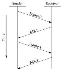
Mechanisms for flow control: Stop and Wait
- It forces the sender to stop and wait after transmission of data frame until the ack is received.
Mechanisms for flow control: Sliding Window
- Both sender and receiver agree on number of data frames after which ack should be sent.
Mechanisms for error control
1) Stop and Wait ARQ
2) Go-Back-N ARQ
3) Selective Repeat ARQ
HDLC
- It is a bit oriented code transparent synchronous data link layer protocol.
- It provides both connection-oriented and connectionless services.
- It is used for point-to-multipoint connections.
- The structure of HDLC frame is:
| Flag(8) | Address (8+) | Control(8/16) | Information(n*8) | FCS(16/32) | Flag (8) |
-HDLC frames can be information, supervisory or unnumbered frames.
- The types of link configurations are:
a) Normal Response Mode
b) Asynchronous Response Mode
c) Asynchronous Balanced Mode
PPP
- It is a data link protocol used to establish a direct connection between two nodes.
- It provides connection authentication, transmission, encryption and compression.
- It is used over Internet access connections.
- The requirement for PPP is that the circuit provided must be duplex.
- The structure of PPP frame is:
| Flag(8) | Address(8) | Control(8) | Protocol(16) | Information(n*8) | Padding(n*8) | FCS(16/32) | Flag (8) |
Data Link Layers - Sub Layers
Media Access Control:
- It is responsible to share physical connection to the network among several computers.
- It helps in frame delimiting and recognition.
- It provides protection against errors.
- It addresses destination stations.
Logical Link Control:
- It provides node to node flow control and error control.
- It provides multiplexing protocols.
- It manages traffic over physical medium.
Channel Allocation Problem
- Channel allocation means which station is permitted the channel next.
- It may be:
a) Static (assignment for long duration)
b) Dynamic (stations continuously compete for allocation)
- In static allocation, channel is requested, data is transferred and channel is released.
- Channel becomes private after allocation.
- Channel can be divided using FDM and TDM.
Multiple Access Protocol
- It is a protocol that coordinate access to the link, which can be used by both wired and wireless network.
- Nodes use multiple access protocols to regulate transmission onto the shared broadcast channel.
- All frames involved in the collision are lost.
Ethernet
- It is a working group and a collection of IEEE standards defining physical layer and MAC sub layer of wired Ethernet.
- It defines LAN access method using CSMA/CD.
- Ethernet is a link layer protocol describing how networked devices on same network can format data for transmission and how to put that data on the network connection.
FDDI; ALOHA; VLAN; CSMA/CD; Token Bus; Token Ring and Wireless LAN
FDDI
- FDDI stands for Fiber Distributed Data Interface.
- It is a set of ANSI and ISO standards for data transmission on fiber optic in LAN.
- FDDI protocol is based on token ring protocol.
- It consists of two token rings.
- Primary ring offers up to 100 Mbps capacity.
- Secondary ring is for backup if primary ring fails.
- It offers circuit switched service to the network.
ALOHA
- ALOHA stands for Additive Links On-line Hawaii Area.
- It uses random method of medium access and UHF for its operation.
- The following assumptions are made:
a) All the frames have same length.
b) Stations can not generate a frame while transmitting.
c) The population of stations attempts to transmit according to Poisson Distribution.
VLAN
- VLAN stands for Virtual Local Area Network.
- It is a broadcast domain partitioned and isolated in a computer network.
- Network equipment is configured to subdivided network into VLAN.
- It allows network administrators to group hosts together if the hosts are not on the network switch also.
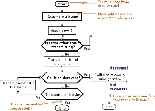
CSMA/CD
- CSMA/CD stands for Carrier Sense Multiple Access with Collision Detection.
- It is a media access control method which uses carrier sensing scheme in transmitting station to detect collision.
- If collision is detected, station stops transmitting the frame, transmits the jam signal and waits for random time interval before trying to resend the frame.
IEEE 802.4 (Token Bus)
- Token bus is a network implementing token ring protocol over a virtual ring on a coaxial cable.
- A token is passed around the network nodes and the node with token is only able to transmit.
- If a node does not have anything to send, it passes token to next node on virtual ring.
- Each node must know address of its neighbor in the ring.
- The endpoints of the bus do not meet to form a physical ring.
IEEE 802.5 (Token Ring)
- Token ring is a LAN communication protocol using 3 byte frame called token that travels around a logical ring of nodes.
- It provides fair access for all stations and eliminates the collisions.
Multiple Access in 802.5
- Time Division Multiple Access is used.
- Stations access channel in rounds with the help of tokens.
- Each station gets fixed length slot in each time.
- The unused slots go idle.
IEEE 802.1 (Wireless LAN)
- Wireless LAN is a LAN that uses radio waves to communicate.
- It is defined in standard IEEE 802.1.
- by SURAJ AWAL

Ⓒ Copyright ESign Technology 2019. A Product of ESign Technology. All Rights Reserved.